
 24199
24199Do you know why stepper motor wires have different colors and what different colors stand for? Understanding the meaning of stepper motor wire colors is essential for beginners delving into the world of motor control.
Stepper motor wire colors indicate the connections to the motor's coils.
The stepper motor wire colors can vary depending on the specific motor and manufacturer. However, in general, the color coding of stepper motor wires typically follows a standard convention.
There are 4 basic stepper motor wire colors and 3 types of stepper motor wire options you can choose from.
These stepper motor color codes are often used in bipolar stepper motors, which have two phases (A and B) or four phases (A, B, C, and D).
The exact order of the wire pairs (e.g., Black/Green or Green/Black) does not matter, but keeping the pairs together on the left side and red/blue together on the right side is important.
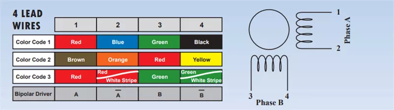
In 4-wire stepper motors, the coils are typically connected internally, resulting in a simplified wiring configuration.
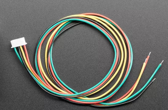
The wire colors commonly found in 4-wire stepper motors are red, blue, green, and black, representing the motor's coil A, coil B, coil C, and coil D, respectively.
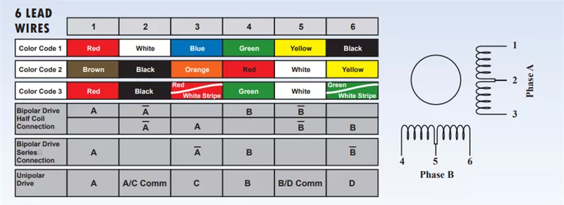
6-wire stepper motors allow for connection options: bipolar series or bipolar parallel, providing flexibility in motor control.
In 6-wire stepper motors, the additional white wire serves as the common wire, while the other colors (red, blue, green, and black) represent coil A+, coil A-, coil B+, and coil B-.
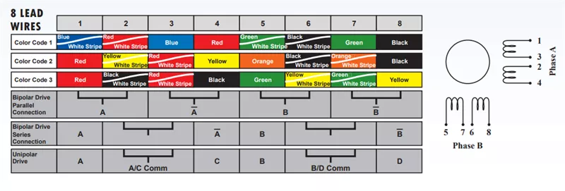
8-wire stepper motors offer even more wiring possibilities, including the option for unipolar operation.
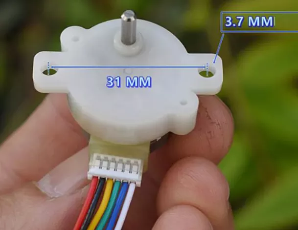
8-Wire Stepper Motor Wire Colors: 8-wire stepper motors have a wider range of wire colors, including red, orange, yellow, brown, black, white, green, and blue, each representing specific coil connections (A+, A-, B+, B-, C+, C-, D+, and D-).
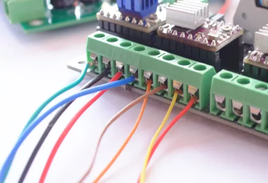
1. Determine the wire pairs or connections at the ends of each coil to wire up the stepper motor accurately. Proper wiring is crucial for stepper motors to function correctly and move in the desired direction.
2. The coil sequence and polarity are essential factors to consider for proper motor movement. Identify the different phases or coils of the motor, enabling correct phase connections for optimal motor operation.
Here are the wiring diagrams for 4/6/8-wire stepper motors, illustrating the colors and connections required for different wiring configurations.
Wiring a stepper motor incorrectly can lead to a variety of problems.
Chipsmall Limited consists of a professional team with an average of over 20 years of expertise in the distribution of electronic components. The main products comprise ICs, resistors, capacitors, modules, potentiometers, IC sockets, relays, connectors, and so on.

Visit Chipsmall to find the products you need.
Add them to your RFQ cart and click on submit. We will respond ASAP within 24 hours.
Stepper motor wire colours carry important information about coil connections in motor control. The standard color convention assigns specific colors to represent different coils or phases. Understanding these stepper motor wire color codes allow for accurate wiring and proper motor function.
Disclaimer: The views and opinions expressed by individual authors or forum participants on this website do not represent the views and opinions of Chipsmall, nor do they represent Chipsmall's official policy.

share this blog to:
Chipsmall will provide you real-time product updates, limited-time deals.


Copyright © 2004-2026 Chipsmall.com All Rights Reserved.

Feedback
We appreciate your engagement with Chipsmall's products and services. Your opinion matters to us! Kindly take a moment to complete the form below. Your valuable feedback ensures that we consistently deliver the exceptional service you deserve. Thank you for being part of our journey towards excellence.

