
 32909
32909A relay is a small electrical switch controlled by electricity. It uses a small current to turn a larger current on or off. Think of it as a remote control for electricity—it allows one circuit to safely control another without being directly connected.
Relays are used almost everywhere. In cars, they control headlights, fuel pumps, and cooling fans. In factories, they help operate heavy machines and motors. At home, they’re found in HVAC systems, smart lighting, and garage doors.
Among different types, the 5-pin relay is one of the most common and versatile. It can switch between two circuits, making it useful in many applications. Today, we’ll explain how a 5 pin relay works, its wiring diagram, and where it is used.
A 5-pin relay is an electromechanical switch that uses an electromagnet to operate its contacts. It allows a low-power control signal to switch a high-power circuit on or off. These relays are widely used in automotive, industrial, and residential systems. Understanding their pin configuration and wiring is essential for using them effectively.
A 5 pin relay is built from several key parts. Each component plays an important role in making the relay work safely and efficiently.
Electromagnetic Coil: This is a copper wire wrapped around an iron core. When electricity flows through the coil, it produces a magnetic field. This magnetic field is what powers the relay and allows it to switch circuits on or off.
Armature: The armature is a small movable piece of metal inside the relay. When the magnetic field from the coil is active, the armature moves and pushes the relay contacts to change their state.
Contacts: These are the switching points of the relay. A 5 pin relay has three main contacts:
Common (COM, Pin 30): This is the central terminal that connects to either the NO or NC pin.
Normally Open (NO, Pin 87): This contact connects to COM only when the relay coil is energized. It is often used for powering devices only when the relay is switched on.
Normally Closed (NC, Pin 87a): This contact is connected to COM when the relay is not powered. It keeps the circuit closed until the relay is activated.
Spring: The spring pushes the armature back into its original position once the coil is de-energized. This ensures the relay returns to its normal state automatically.
Housing: The outer case is usually made of durable plastic or metal. It protects the internal parts of the relay from dust, moisture, and mechanical damage.
Terminals: These are the five external pins of the relay (85, 86, 30, 87, and 87a). Each terminal has a specific role in wiring the relay correctly. Pins 85 and 86 connect to the coil, while pins 30, 87, and 87a are for the switching circuit.

A 5 pin relay operates like a switch that changes connections depending on whether it is powered or not. It has two main states: de-energized (OFF) and energized (ON).
In this state, there is no voltage applied to the coil terminals (pins 85 and 86).
The internal spring keeps the armature in its normal position.
Pin 30 (Common) is connected to Pin 87a (Normally Closed, NC).
Pin 87 (Normally Open, NO) is not connected to anything.
This means that any device wired to Pin 87a will receive power and stay ON by default, while the device on Pin 87 will remain OFF.
Example: Imagine a car’s daytime running light is connected to Pin 87a. Since the relay is off, the light stays on by default.
When voltage is applied across the coil pins (85 = ground, 86 = positive), the coil creates a magnetic field.
This magnetic field pulls the armature, switching the connection inside the relay.
Now, Pin 30 disconnects from 87a (NC) and instead connects to Pin 87 (NO).
As a result, the device on Pin 87 turns ON, while the device on Pin 87a turns OFF.
Example: When you turn on the car’s headlights, the relay is energized. The running light (on 87a) turns off, and the headlights (on 87) switch on.
This switching action makes the 5 pin relay very flexible. It can control two circuits with one relay:
A normally powered device (connected to NC, Pin 87a).
A device that only powers on when needed (connected to NO, Pin 87).
Pin connections:
Pin 85 → Ground (–)
Pin 86 → Positive (+) through a switch (to power the coil)
Pin 30 → Positive power input from battery or supply
Pin 87 → Connect to the device that turns ON only when the relay is powered
Pin 87a → Connect to the device that stays ON until the relay is powered
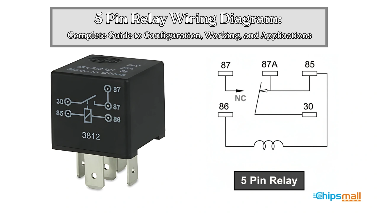
Before you look at a 5 pin relay wiring diagram, it’s important to know the common symbols. These symbols act like a “map key,” helping you understand what each part of the diagram means.

Relay: Shown as a rectangle with a coil and contact lines. Pins are marked as 30, 85, 86, 87, and 87a.
Switch: A line with a small break, showing it can open or close the circuit.
Battery: Two parallel lines, one long and one short. The long line is positive (+).
Load (Device): Shown with different icons, like a light bulb for a lamp or a circle with “M” for a motor.
Wires: Straight lines that connect the parts together.
Ground: Shown with three horizontal lines stacked or a downward triangle symbol.
Find the relay: Look for the rectangle and check the pin numbers.
Trace the coil circuit: Follow pins 85 and 86 to see how the relay is switched on.
Check the power source: Find the battery symbol and note positive and negative sides.
Trace the load circuit: Follow pin 30 to either pin 87 (Normally Open) or 87a (Normally Closed), then to the device.
Understand the logic: Notice if the diagram shows Normally Open or Normally Closed. This tells you when the device will turn ON or OFF.
Identify the Pins: The first step is to look closely at your relay and identify the pin numbers. A standard 5-pin relay will have the numbers 85, 86, 30, 87, and 87a marked on its body or near the terminals. Each number has a specific role: 85 and 86 are for the coil (control side), 30 is the common input, and 87/87a are the output terminals. Recognizing these pins correctly is very important before making any connections.
Connect the Coil: The coil is what activates the relay. Connect Pin 85 to the ground (negative terminal) of your power source, such as a car battery. Then connect Pin 86 to the control switch or control signal. This could be a button, ignition line, or an electronic control unit (ECU) signal. When voltage flows through pins 85 and 86, the coil energizes and makes the relay switch from its normal position.
Wire the Common Terminal: Next, connect Pin 30 to your main power supply. This pin acts as the “input” for the relay. The power connected here will eventually be directed to either pin 87 or 87a depending on whether the relay is on or off. For safety, this power line is often connected through a fuse to protect your circuit.
Choose Your Output: Now decide how you want your device to work. If you want the device to be off by default and only turn on when the relay is powered, connect it to Pin 87 (Normally Open, NO). On the other hand, if you want the device to be on by default and turn off when the relay is powered, connect it to Pin 87a (Normally Closed, NC). This flexibility is why the 5-pin relay is more versatile than a 4-pin relay.
Test the Relay: Finally, test the relay to make sure everything is working correctly. When the relay is OFF (coil not powered), Pin 30 should be connected to Pin 87a, meaning the device wired to 87a will run. When the relay is ON (coil powered), Pin 30 disconnects from 87a and connects to Pin 87, turning on the device wired there. This simple switching action allows you to control high-power devices safely with a low-power signal.

To wire a 5-pin relay correctly, start by identifying the pins: 30 (Common), 87 (Normally Open), 87a (Normally Closed), 85 (Coil Ground), and 86 (Coil Power). Connect pin 85 to ground and pin 86 to the control switch or power source. Attach the load to pin 30. If you want the device to turn on only when the relay is energized, connect it to pin 87 (NO). If the device should stay on when the relay is off, connect it to pin 87a (NC). Once wired, apply voltage to the coil terminals (85 and 86) and confirm the relay switches properly between pins 87 and 87a. For safety, make sure all connections are secure and consider adding a diode across the coil to prevent voltage spikes.
Check coil resistance: Measure across pins 85 and 86 with a multimeter.
Verify control voltage: Confirm power reaches the coil when the switch is ON.
Listen for a click: If the relay clicks but doesn’t switch, test continuity on the output pins.
Inspect wiring: Tighten or replace loose, weak, or corroded connections.
Perform maintenance: Clean or replace relays with burnt or worn contacts.
Automotive: In vehicles, 5-pin relays are very common because they help control high-power devices with low-power switches. They keep circuits safe and efficient.
Headlights: A 5-pin relay allows the driver to switch between low and high beams easily without burning out the switch.
Horn circuits: The relay lets the horn sound loudly while protecting the steering wheel switch from damage.
Fuel pumps: It controls the power going to the pump, ensuring it only runs when the engine needs fuel.
Cooling fans: Relays turn fans on or off automatically depending on the engine’s temperature.
Auxiliary lights: Extra fog lights or off-road lights use relays to draw power safely without overloading the dashboard switch.
Industrial: In industries, 5-pin relays are used to handle heavy electrical loads and to automate processes. They make machines more reliable and safe to operate.
Motor control: Relays help start, stop, and reverse motors without requiring large manual switches.
Solenoid valves: They control the opening and closing of valves in systems like hydraulics and pneumatics.
Security systems: Relays connect alarms, sensors, and locks, allowing them to work together smoothly.
Process automation: Factories use relays to automate steps in production lines, making the work faster and reducing human error.
Residential: At home, 5-pin relays are often used in smart systems that improve safety, comfort, and energy efficiency.
Smart lighting and HVAC: Relays help control lights, fans, and air conditioning units remotely, saving energy and making homes smarter.
Security gates/doors: They allow remote control of gates and electric doors, improving convenience and safety.
Irrigation systems (sprinklers, pumps): Relays turn water pumps or sprinklers on and off at set times, making it easy to manage gardens and lawns.
When you need reliable electronic parts, it’s important to source them from trusted distributors. Chipsmall is a professional supplier that provides genuine components such as 5-pin relays, integrated circuits (ICs), connectors, capacitors, resistors, and potentiometers. Engineers, hobbyists, and manufacturers often choose Chipsmall because it provides a wide selection of both common and hard-to-find components. The company ensures the authenticity of its parts, which reduces the risk of counterfeit components. Other reputable global distributors include Mouser Electronics, Digi-Key, and RS Components, which also offer reliable shipping and datasheets.
FAQs: 5-Pin Relay Wiring Diagram
Q1. What does a 5-pin relay wiring diagram show?
A: A 5-pin relay wiring diagram shows how to connect all five pins (85, 86, 30, 87, 87a) to the power source, control switch, and load. It helps you understand which devices turn on or off when the relay is energized.
Q2. How do I read a 5-pin relay diagram?
A: Look for the rectangle symbol representing the relay. Pins 85 and 86 connect to the coil, pin 30 is the common input, pin 87 is normally open (NO), and pin 87a is normally closed (NC). Trace the lines to see how power flows to your device.
Q3. What is the difference between NO and NC in the diagram?
A: NO (Normally Open, pin 87) is connected to the common pin 30 only when the relay is powered. NC (Normally Closed, pin 87a) stays connected to pin 30 when the relay is off. The diagram helps you decide which devices to connect to each pin.
Q4. Can I use a diagram to troubleshoot my relay circuit?
A: Yes. The diagram shows the correct connections and switching logic, so you can check if the coil and load are wired correctly and find any loose wires or mistakes.
Q5. Do I need a relay diagram for every project?
A: It’s highly recommended. A wiring diagram ensures you connect the relay correctly, preventing damage to the relay, devices, or control circuits.
Q6. Where can I find accurate relay wiring diagrams?
A. Reliable component suppliers like Chipsmall provide datasheets and diagrams for their relays. Manufacturer datasheets usually have clear wiring illustrations and pin configurations.
A 5-pin relay is a key component for controlling electrical circuits with precision. It uses a small control signal to safely switch larger currents, making it essential in cars, machines, and home projects. Understanding the pins, internal parts, how to read a 5-pin relay wiring diagram ensures devices are connected correctly and work as intended.
So, follow the proper wiring steps, double-check connections, and test the relay to keep your circuits safe, reliable, and efficient.
Disclaimer: The views and opinions expressed by individual authors or forum participants on this website do not represent the views and opinions of Chipsmall, nor do they represent Chipsmall's official policy.

share this blog to:
Chipsmall will provide you real-time product updates, limited-time deals.


Copyright © 2004-2026 Chipsmall.com All Rights Reserved.

Feedback
We appreciate your engagement with Chipsmall's products and services. Your opinion matters to us! Kindly take a moment to complete the form below. Your valuable feedback ensures that we consistently deliver the exceptional service you deserve. Thank you for being part of our journey towards excellence.

